APPENDIX K
PRECISION LIGHTWEIGHT GLOBAL POSITIONING SYSTEM RECEIVER
The precision lightweight global positioning system receiver (PLGR) is a highly accurate satellite signal navigation set (referred to in this appendix as AN/PSN-11).
K-1. CONCEPT OF OPERATION
The AN/PSN-11 is designed for battlefield use anywhere in the world. It is sealed watertight for all weather day or night operation. The AN/PSN-11 is held in the left hand and operated with the thumb of the left hand. Capability is included for installation in ground facilities, and air, sea, and land vehicles. The AN/PSN-11 is operated stand-alone using prime battery power and integral antenna. It can be used with external power source and external antenna.
a. The AN/PSN-11 provides the user with position coordinates, time, and navigation information under all conditions, if―
-
No obstructions block the line-of-sight satellite signal from reaching the antenna.
-
Valid crypto keys are used to protect the AN/PSN-11 from intentionally degraded satellite signals.
b. Many data fields, such as elevation, display units of information. The format of the units can be changed to your most familiar format.
c. Map coordinates are entered as a way point. When a way point is selected as a destination, the AN/PSN-11 provides steering indications, azimuth, and range information to the destination. A desired course to a way point is entered. Offset distance from this course line is shown.
d. Up to 999 way points can be entered, stored, and selected as a destination. A route is defined for nav either start-to-end or end-to-start. The route consists of up to nine legs (10 way points) linked together.
K-2. CAPABILITIES
Data provided by the AN/PVS-11 helps complete missions such as:
-
Siting.
-
Surveying.
-
Tactical reconnaissance.
-
Sensor emplacement.
-
Artillery forward observing.
-
Close air support.
-
General navigation.
-
Mechanized maneuvers.
-
Engineer surveying.
-
Amphibious operations.
-
Parachute operations.
-
Signal intelligence.
-
Electronic warfare.
-
Ground-based forward air control.
This data is displayed on the AN/PSN-11display. It is also available from a serial data port.
K-3. CHARACTERISTICS
The AN/PSN-11 is less than 9.5 inches long, 4.1 inches wide, and 2.6 inches deep. It weighs 2.75 pounds with all batteries in place. The small size and lightweight make the set easy to carry and use. The durable plastic case is sealed for all-weather use. The AN/PSN-11 features make it easy to use. (These features are highlighted in the physical description in Figure K-1).
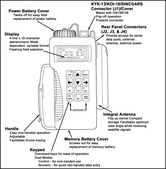
Figure K-1. Physical features.
K-4. SETUP AND CONTROL
Setting up the operation parameters of the PLGR is critical. This section describes the display, procedures, and principles used in setting the AN/PSN-11displays to suit the needs of the user. This display consists of seven pages that allows the user to control the following parameters:
-
Operating mode.
-
Type of satellites to use.
-
Coordinate system.
-
Units.
-
Magnetic variation.
-
Display customization.
-
Navigation Display mode.
-
Elevation hold mode.
-
Time and error formats.
-
Datum.
-
Automatic off timer.
-
Datum port configuration.
-
AutoMark mode.
To set the PLGR up for continuous operation:
a. Turn the PLGR ON. Once it has completed its built-in-test (BIT) press the MENU key and move the cursor to SETUP (Figure K-2). Activate the SETUP function.

Figure K-2. SETUP.
b. The first screen (Figure K-3) allows the operator to set the operating mode and SV-Type. Scroll through the operating modes and select CONT and for the SV-Type Mixed.
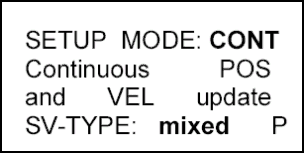
Figure K-3. Operating mode and SV-type.
c. The second screen (Figure K-4) allows the operator to setup the units. Scroll through the available coordinates and select MGRS-New and Metric. For the Elevation select meter and MSL and for the Angle select Degrees and Magnetic.
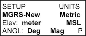
Figure K-4. Setup the units.
d. The third screen (Figure K-5) should be set for the MAGVAR (Magnetic variation or GM Angle for your area). The operator can select Calculate the degree or manually enter degrees as an Easterly or Westerly GM Angle; for example, E021.0 for the TENINO Map Sheet.
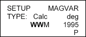
Figure K-5. Magnetic variation or GM angle setup.
e. The fourth screen (Figure K-6) of setup allows the operator to set the Elevation Hold, Time, and Error. The operator should set the ELHOLD to automatic. As for time the operator needs to know, from their present location, how many hours they are ahead of or behind Greenwich Mean Time. For example, during Daylight savings time, Fort Benning, GA. is Loc=Z-0400. To set the ERR, the operator selects -+m to let him know in meters how accurate the PLGR is operating.
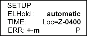
Figure K-6. Set elevation, time, hold, and error.
f. The fifth screen (Figure K-7) of setup allows the operator to set the PLGR Datum to their area of operation and to set the Automatic Off Timer. The PLGR has fifty-two map Datum sets available. The operator should set the PLGR Datum to their area of operation. For example, if your map Datum is WGS-84, the operator sets the PLGR to WGS-84. If the map is 1927 North America Datum, the operator sets the Datum to NAS-C. The automatic timer off is used to turn the PLGR off after a prescribed time once it has acquired a fixed position. The operator should set this mode to OFF.
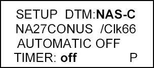
Figure K-7. Set the PLGR Datum.
g. The sixth screen (Figure K-8) in setup is the In/Out Port screen. This page allows the operator to control serial communications, HAVEQUICK and 1PPS options. Select Standard unless otherwise directed and select OFF for Havequick and 1PPS.

Figure K–8. In/out port screen.
h. The seventh screen (Figure K-9) is setup AUTOMARK. This feature allows the operator to have the PLGR periodically wake-up, acquire a position fix, store the position as a way point, or return to the mode of operation it was previously in. The operator should set this mode to OFF. The remaining pages for SETUP are for advance GPS users.
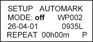
Figure K–9. AUTOMARK setup.
i. Once the PLGR is SETUP, the operator can now obtain a position. This procedure is accomplished by activating the Position (POS) key. The position displayed is OLD information until the receiver collects and calculates satellite data and displays the current position. The receiver must be tracking three satellites to obtain a two-dimensional fix position and four or more satellites for a three-dimensional fix position. The third dimension is elevation.
K-5. WAY POINT OPERATIONS
A way point is the location of a point on a desired course described by coordinates or a physical location. A normal mission consists of a series of way points. The way points available on the AN/PSN-11 are 999 (numbered 01 through 999).
a. This paragraph describes the AN/PSN-11 way point displays and way point operations. The way point display pages are used to perform the following operations:
-
Enter, edit, or review way points.
-
Copy way points.
-
Determine the distance between way points.
-
Calculate a new way point.
-
Clear way points.
-
Define a mission route.
b. To enter a way point, the operator needs to press the way point (WP) key (Figure K-10). When the way point menu appears, the ENTER function flashes. The operator presses the down arrow key to activate this field. Now the operator enters a way point name, grid zone designator, 100,000-meter grid square identifier, 10-digit grid coordinate, and elevation.
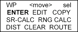
Figure K–10. Enter a way point.
c. To enter a way point name, the operator presses the right arrow key until the first letter of the word UNUSED(WP#) is flashing (Figure K-11). Scroll up or down through the alphabet changing the letter U to whatever is desired. For example, if the operator wanted to name their way point NORTH STAR, the operator scrolls down the alphabet until the letter U is changed to the letter N (Figure K-12). The operator repeats this process for the remaining letters.

Figure K–11. Unused.
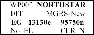
Figure K-12. Change a name.
d. Second line, the operator enters the grid zone designator for their area of operation. For example, the Fort Benning area falls in the 16S zone.
e. Third line, the operator must enter a 10-digit grid coordinate with its 100,000-meter grid square identifier. For example, if the way point location is Offutt Lake, Tenino map sheet, the 100,000-meter grid square identifier is EG. Then, the operator plots the grid coordinates on the map and enters it into the PLGR.
NOTE:
th and 10th digit entered is a zero (0).
f. For the fourth line, if the elevation of the way point is known, the operator can enter it. If the elevation is not known the operator can just leave the data as zero or No EL. The operator moves the cursor until the Up and Down arrow symbol appears before the letter P or N in bottom right corner. When activating the down arrow key the operator stores the way point into the PLGR’s memory. The PLGR notifies the operator that the way point has been stored.
NOTE:
Figure K-12).
K-6. NAVIGATION
Navigation (nav) is using the AN/PSN-11 to find your present position, relative to other points. The AN/PSN-11 provides azimuth, range, and steering information in a variety of formats. There are four navigation display modes that may be accessed and selected. The navigation display mode selected determines the type of information shown on the navigation displays. These navigation displays give the user the most useful information for a certain mission profile: SLOW, 2D FAST, 3D FAST OR CUSTOM.
-
In SLOW nav mode, the AN/PSN-11 performs two-dimensional (2D) nav. Slow nav mode is used for land or sea nav, when the user cannot maintain the minimum speed necessary (about 1.5 kmph).
-
In 2D FAST nav mode, the AN/PSN-11 performs two-dimensional (2D) nav. 2D FAST nav mode is used for land or sea nav, when the user can maintain the minimum speed necessary for GPS to compute navigation parameters based on velocity.
-
In 3D FAST nav mode, the AN/PSN-11 performs three-dimentional (3D) nav. 3D FAST nav mode has an APPROACH sub-mode. 3D FAST nav mode is used for air nav, when the user can travel in three dimensions and can maintain the minimum speed necessary for GPS to compute navigation parameters based on velocity.
-
In CUSTOM nav mode, the AN/PSN-11 performs the users navigational display pages as so desired. It can be set-up to support the individual user’s performances or mission requirements. The following custom display modes are available:
-
Direct.
-
Course To.
-
Course From.
-
Route.
-
Approach.
-
To navigate with the PLGR on land in a Dead-Reckoning method, the PLGR nav mode is accomplished as follows.
a. The operator presses the NAV key activating the nav function. The first screen that appears is the nav mode (Figure K-13). For example, SLOW, 2D FAST, 3D FAST, CUSTOM, DIRECT, CRS TO, and CRS FROM.

Figure K–13. Navigation mode.
b. The operator selects the 2D FAST and DIRECT. The second line is the way point desired to be navigated. (Scroll through the way points that are stored to choose the desired way point.)
c. To see the azimuth that the navigator should be traveling on, go to the next page by pressing the down arrow key (Figure K-14). This page tells the navigator what azimuth they are heading on (TRK=tracking), and the actual azimuth the navigator should be heading on (AZ). The fourth line tells the navigator Steering (STR). A direction (< >) and a number of degrees the navigator needs to move to travel on their actual azimuth.
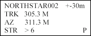
Figure K–14. Azimuth.
d. The third screen (Figure K-15) tells the navigator the range or distance to their way point and how much time (TTG2) it will take them to get to their way point. This page also lets the navigator know what is the elevation difference from their present location to the way point and by how much they will miss their way point by (MMD).
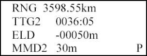
Figure K–15. Range or distance.
Land Navigation Training Software
- Chapter 1: TRAINING STRATEGY
- Chapter 2: MAPS
- Chapter 3: MARGINAL INFORMATION AND SYMBOLS
- Chapter 4: GRIDS
- Chapter 5: SCALE AND DISTANCE
- Chapter 6: DIRECTION
- Chapter 7: OVERLAYS
- Chapter 8: AERIAL PHOTOGRAPHS
- Chapter 9: NAVIGATION EQUIPMENT AND METHODS
- Chapter 10: ELEVATION AND RELIEF
- Chapter 11: TERRAIN ASSOCIATION
- Chapter 12: MOUNTED LAND NAVIGATION
- Chapter 13: NAVIGATION IN DIFFERENT TYPES OF TERRAIN
- Chapter 14: UNIT SUSTAINMENT
- Appendix A: FIELD SKETCHING
- Appendix B: MAP FOLDING TECHNIQUES
- Appendix C: UNITS OF MEASURE AND CONVERSION FACTORS
- Appendix D: JOINT OPERATIONS GRAPHICS
- Appendix E: EXPORTABLE TRAINING MATERIAL
- Appendix F: ORIENTEERING
- Appendix G: M2 COMPASS
- Appendix H: ADDITIONAL AIDS
- Appendix I: FOREIGN MAPS
- Appendix J: GLOBAL POSITIONING SYSTEM
- Appendix K: PRECISION LIGHTWEIGHT GLOBAL POSITIONING SYSTEM RECEIVER
- Map Reading and Land Navigation GLOSSARY
- Map Reading and Land Navigation REFERENCES