Chapter 5
SCALE AND DISTANCE
A map is a scaled graphic representation of a portion of the earth’s surface. The scale of the map permits the user to convert distance on the map to distance on the ground or vice versa. The ability to determine distance on a map, as well as on the earth’s surface, is an important factor in planning and executing military missions.
5-1. REPRESENTATIVE FRACTION
The numerical scale of a map indicates the relationship of distance measured on a map and the corresponding distance on the ground. This scale is usually written as a fraction and is called the representative fraction. The RF is always written with the map distance as 1 and is independent of any unit of measure. (It could be yards, meters, inches, and so forth. ) An RF of 1/50,000 or 1:50,000 means that one unit of measure on the map is equal to 50,000 units of the same measure on the ground.
a. The ground distance between two points is determined by measuring between the same two points on the map and then multiplying the map measurement by the denominator of the RF or scale (Figure 5-1).
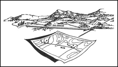
Figure 5-1. Converting map distance to ground distance.
EXAMPLE:
The map scale is 1:50,000
RF = 1/50,000
The map distance from point A to point B is 5 units
5 x 50,000 = 250,000 units of ground distance
b. Since the distance on most maps is marked in meters and the RF is expressed in this unit of measurement in most cases, a brief description of the metric system is needed. In the metric system, the standard unit of measurement is the meter.
1 meter contains 100 centimeters (cm).
100 meters is a regular football field plus 10 meters.
1,000 meters is 1 kilometer (km).
10 kilometers is 10,000 meters.
Appendix C contains the conversion tables.
c. The situation may arise when a map or sketch has no RF or scale. To be able to determine ground distance on such a map, the RF must be determined. There are two ways to do this:
(1) Comparison with Ground Distance.
(a) Measure the distance between two points on the map—map distance (MD).
(b) Determine the horizontal distance between these same two points on the ground—ground distance (GD).
(c) Use the RF formula and remember that RF must be in the general form:
RF
=
1
=
MD
——
——
X
GD
(d) Both the MD and the GD must be in the same unit of measure and the MD must be reduced to 1.
EXAMPLE:
MD = 4. 32 centimeters
GD = 2. 16 kilometers
(216,000 centimeters)
RF
=
1
=
4. 32
——
——
X
216,000
or
216,000
=
50,000
——
4. 32
therefore
RF
=
1
or
1:50,000
——
50,000
(2) Comparison With Another Map of the Same Area that Has an RF.
(a) Select two points on the map with the unknown RF. Measure the distance (MD) between them.
(b) Locate those same two points on the map that have the known RF. Measure the distance (MD) between them. Using the RF for this map, determine GD, which is the same for both maps.
(c) Using the GD and the MD from the first map, determine the RF using the formula:
RF
=
1
=
MD
——
——
X
GD
d. Occasionally it may be necessary to determine map distance from a known ground distance and the RF:
MD
=
GD
————————
Denominator or RF
Ground Distance = 2,200 meters
RF = 1:50,000
MD
=
2,200 meters
————————
50,000
MD = 0. 044 meters x 100 (centimeters per meter)
MD = 4. 4 centimeters
e. When determining ground distance from a map, the scale of the map affects the accuracy. As the scale becomes smaller, the accuracy of measurement decreases because some of the features on the map must be exaggerated so that they may be readily identified.
5-2. GRAPHIC (BAR) SCALES
A graphic scale is a ruler printed on the map and is used to convert distances on the map to actual ground distances. The graphic scale is divided into two parts. To the right of the zero, the scale is marked in full units of measure and is called the primary scale. To the left of the zero, the scale is divided into tenths and is called the extension scale. Most maps have three or more graphic scales, each using a different unit of measure (Figure 5-2). When using the graphic scale, be sure to use the correct scale for the unit of measure desired.
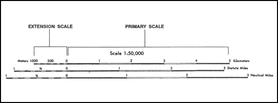
Figure 5-2. Using a graphic (bar) scale.
a. To determine straight-line distance between two points on a map, lay a straight-edged piece of paper on the map so that the edge of the paper touches both points and extends past them. Make a tick mark on the edge of the paper at each point (Figure 5-3).
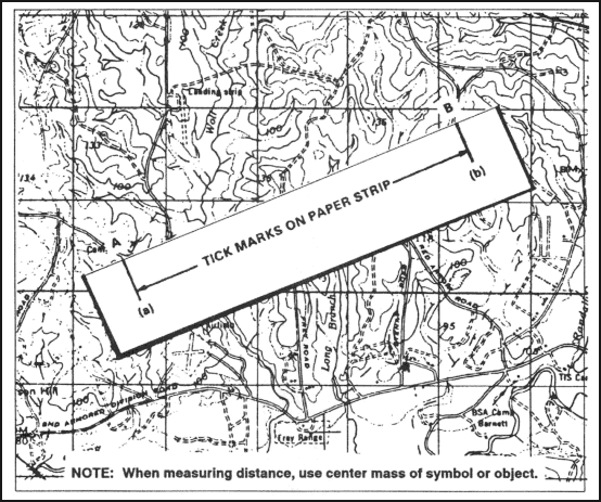
Figure 5-3. Transferring map distance to paper strip.
b. To convert the map distance to ground distance, move the paper down to the graphic bar scale, and align the right tick mark (b) with a printed number in the primary scale so that the left tick mark (a) is in the extension scale (Figure 5-4).
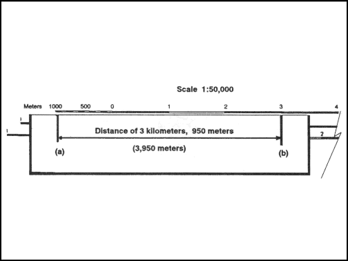
Figure 5-4. Measuring straight-line map distance.
c. The right tick mark (b) is aligned with the 3,000-meter mark in the primary scale, thus the distance is at least 3,000 meters. To determine the distance between the two points to the nearest 10 meters, look at the extension scale. The extension scale is numbered with zero at the right and increases to the left. When using the extension scale, always read right to left (Figure 5-4). From the zero left to the beginning of the first shaded area is 100 meters. From the beginning of the shaded square to the end of the shaded square is 100 to 200 meters. From the end of the first shaded square to the beginning of the second shaded square is 200 to 300 meters. Remember, the distance in the extension scale increases from right to left.
d. To determine the distance from the zero to tick mark (a), divide the distance inside the squares into tenths (Figure 5-4). As you break down the distance between the squares in the extension scale into tenths, you will see that tick mark (a) is aligned with the 950-meter mark. Adding the distance of 3,000 meters determined in the primary scale to the 950 meters you determined by using the extension scale, we find that the total distance between points (a) and (b) is 3,950 meters.
e. To measure distance along a road, stream, or other curved line, the straight edge of a piece of paper is used. In order to avoid confusion concerning the point to begin measuring from and the ending point, an eight-digit coordinate should be given for both the starting and ending points. Place a tick mark on the paper and map at the beginning point from which the curved line is to be measured. Align the edge of the paper along a straight portion and make a tick mark on both map and paper when the edge of the paper leaves the straight portion of the line being measured (Figure 5-5A).
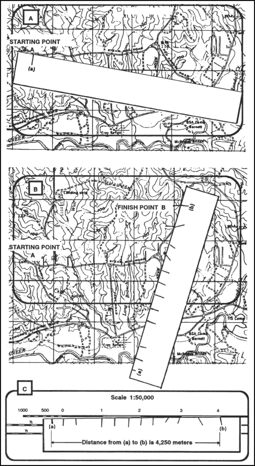
Figure 5-5. Measuring a curved line.
f. Keeping both tick marks together (on paper and map), place the point of the pencil close to the edge of the paper on the tick mark to hold it in place and pivot the paper until another straight portion of the curved line is aligned with the edge of the paper. Continue in this manner until the measurement is completed (Figure 5-5B).
g. When you have completed measuring the distance, move the paper to the graphic scale to determine the ground distance. The only tick marks you will be measuring the distance between are tick marks (a) and (b). The tick marks in between are not used (Figure 5-5C).
h. There may be times when the distance you measure on the edge of the paper exceeds the graphic scale. In this case, there are different techniques you can use to determine the distance.
(1) One technique is to align the right tick mark (b) with a printed number in the primary scale, in this case the 5. You can see that from point (a) to point (b) is more than 6,000 meters when you add the 1,000 meters in the extension scale. To determine the exact distance to the nearest 10 meters, place a tick mark (c) on the edge of the paper at the end of the extension scale (Figure 5-6A). You know that from point (b) to point (c) is 6,000 meters. With the tick mark (c) placed on the edge of the paper at the end of the extension scale, slide the paper to the right. Remember the distance in the extension is always read from right to left. Align tick mark (c) with zero and then measure the distance between tick marks (a) and (c). The distance between tick marks (a) and (c) is 420 meters. The total ground distance between start and finish points is 6,420 meters (Figure 5-6B).
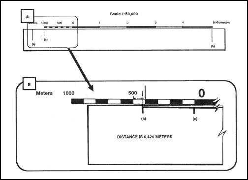
Figure 5-6. Determining the exact distance.
(2) Another technique that may be used to determine exact distance between two points when the edge of the paper exceeds the bar scale is to slide the edge of the paper to the right until tick mark (a) is aligned with the edge of the extension scale. Make a tick mark on the paper, in line with the 2,000-meter mark (c) (Figure 5-7A). Then slide the edge of the paper to the left until tick mark (b) is aligned with the zero. Estimate the 100-meter increments into 10-meter increments to determine how many meters tick mark (c) is from the zero line (Figure 5-7B). The total distance would be 3,030 meters.
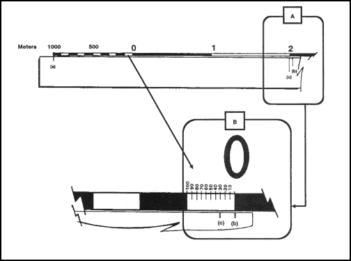
Figure 5-7. Reading the extension scale.
(3) At times you may want to know the distance from a point on the map to a point off the map. In order to do this, measure the distance from the start point to the edge of the map. The marginal notes give the road distance from the edge of the map to some towns, highways, or junctions off the map. To determine the total distance, add the distance measured on the map to the distance given in the marginal notes. Be sure the unit of measure is the same.
(4) When measuring distance in statute or nautical miles, round it off to the nearest one-tenth of a mile and make sure the appropriate bar scale is used.
(5) Distance measured on a map does not take into consideration the rise and fall of the land. All distances measured by using the map and graphic scales are flat distances. Therefore, the distance measured on a map will increase when actually measured on the ground. This must be taken into consideration when navigating across country.
i. The amount of time required to travel a certain distance on the ground is an important factor in most military operations. This can be determined if a map of the area is available and a graphic time-distance scale is constructed for use with the map as follows:
R = Rate of travel (speed)
T
=
Time
D = Distance (ground distance)
T
=
D
——
R
For example, if an infantry unit is marching at an average rate (R) of 4 kilometers per hour, it will take about 3 hours (T) to travel 12 kilometers.
12 (D)
=
3 (T)
——
4 (R)
j. To construct a time-distance scale (Figure 5-8A), knowing your length of march, rate of speed, and map scale, that is, 12 kilometers at 3 kilometers per hour on a 1:50,000-scale map, use the following process:
(1) Mark off the total distance on a line by referring to the graphic scale of the map or, if this is impracticable, compute the length of the line as follows:
(a) Convert the ground distance to centimeters: 12 kilometers x 100,000 (centimeters per kilometer) = 1,200,000 centimeters.
(b) Find the length of the line to represent the distance at map scale—
MD
=
1
=
1,200,000
= 24 centimeters
————
————
50,000
50,000
(c) Construct a line 24 centimeters in length (Figure 5-8A).
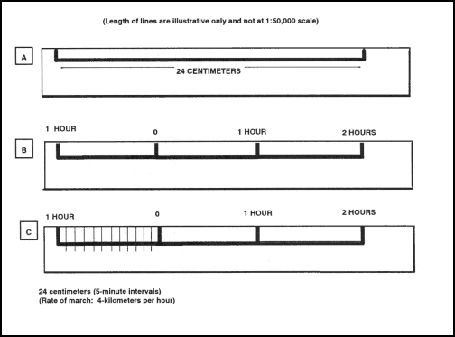
Figure 5-8. Constructing a time-distance scale.
(2) Divide the line by the rate of march into three parts (Figure 5-8B), each part representing the distance traveled in one hour, and label.
(3) Divide the scale extension (left portion) into the desired number of lesser time divisions—
1-minute divisions — 60
**
5-minute divisions — 12
**
10-minute divisions — 6
(4) Figure 5-8C shows a 5-minute interval scale. Make these divisions in the same manner as for a graphic scale. The completed scale makes it possible to determine where the unit will be at any given time. However, it must be remembered that this scale is for one specific rate of march only, 4 kilometers per hour.
5-3. OTHER METHODS
Determining distance is the most common source of error encountered while moving either mounted or dismounted. There may be circumstances where you are unable to determine distance using your map or where you are without a map. It is therefore essential to learn methods by which you can accurately pace, measure, use subtense, or estimate distances on the ground.
a. Pace Count. Another way to measure ground distance is the pace count. A pace is equal to one natural step, about 30 inches long. To accurately use the pace count method, you must know how many paces it takes you to walk 100 meters. To determine this, you must walk an accurately measured course and count the number of paces you take. A pace course can be as short as 100 meters or as long as 600 meters. The pace course, regardless of length, must be on similar terrain to that you will be walking over. It does no good to walk a course on flat terrain and then try to use that pace count on hilly terrain. To determine your pace count on a 600-meter course, count the paces it takes you to walk the 600 meters, then divide the total paces by 6. The answer will give you the average paces it takes you to walk 100 meters. It is important that each person who navigates while dismounted knows his pace count.
(1) There are many methods to keep track of the distance traveled when using the pace count. Some of these methods are: put a pebble in your pocket every time you have walked 100 meters according to your pace count; tie knots in a string; or put marks in a notebook. Do not try to remember the count; always use one of these methods or design your own method.
(2) Certain conditions affect your pace count in the field, and you must allow for them by making adjustments.
(a) Slopes. Your pace lengthens on a downslope and shortens on an upgrade. Keeping this in mind, if it normally takes you 120 paces to walk 100 meters, your pace count may increase to 130 or more when walking up a slope.
(b) Winds. A head wind shortens the pace and a tail wind increases it.
(c) Surfaces. Sand, gravel, mud, snow, and similar surface materials tend to shorten the pace.
(d) Elements. Falling snow, rain, or ice cause the pace to be reduced in length.
(e) Clothing. Excess clothing and boots with poor traction affect the pace length.
(f) Visibility. Poor visibility, such as in fog, rain, or darkness, will shorten your pace.
b. Odometer. Distances can be measured by an odometer, which is standard equipment on most vehicles. Readings are recorded at the start and end of a course and the difference is the length of the course.
(1) To convert kilometers to miles, multiply the number of kilometers by 0. 62.
EXAMPLE:
16 kilometers = 16 x 0. 62 = 9. 92 miles
(2) To convert miles to kilometers, divided the number of miles by 0. 62.
EXAMPLE:
10 miles = 10 divided by 0. 62 = 16. 12 kilometers
c. Subtense. The subtense method is a fast method of determining distance and yields accuracy equivalent to that obtained by measuring distance with a premeasured piece of wire. An advantage is that a horizontal distance is obtained indirectly; that is, the distance is computed rather than measured. This allows subtense to be used over terrain where obstacles such as streams, ravines, or steep slopes may prohibit other methods of determining distance.
(1) The principle used in determining distance by the subtense method is similar to that used in estimating distance by the mil relation formula. The field artillery application of the mil relation formula involves only estimations. It is not accurate enough for survey purposes. However, the subtense method uses precise values with a trigonometric solution. Subtense is based on a principle of visual perspective—the farther away an object, the smaller it appears.
(2) The following two procedures are involved in subtense measurement:
-
Establishing a base of known length.
-
Measuring the angle of that base by use of the aiming circle.
(3) The subtense base may be any desired length. However, if a 60-meter base, a 2-meter bar, or the length of an M16A1 or M16A2 rifle is used, precomputed subtense tables are available. The M16 or 2-meter bar must be held horizontal and perpendicular to the line of sight by a soldier facing the aiming circle. The instrument operator sights on one end of the M16 or 2-meter bar and measures the horizontal clockwise angle to the other end of the rifle or bar. He does this twice and averages the angles. He then enters the appropriate subtense table with the mean angle and extracts the distance. Accurate distances can be obtained with the M16 out to approximately 150 meters, with the 2-meter bar out to 250 meters, and with the 60-meter base out to 1,000 meters. If a base of another length is desired, a distance can be computed by using the following formula:
Distance
=
1/2 (base in meters)
————————
Tan (1/2) (in mils)
d. Estimation. At times, because of the tactical situation, it may be necessary to estimate range. There are two methods that may be used to estimate range or distance.
(1) 100-Meter Unit-of-Measure Method. To use this method, the soldier must be able to visualize a distance of 100 meters on the ground. For ranges up to 500 meters, he determines the number of 100-meter increments between the two objects he wishes to measure. Beyond 500 meters, the soldier must select a point halfway to the object(s) and determine the number of 100-meter increments to the halfway point, then double it to find the range to the object(s) (Figure 5-9).
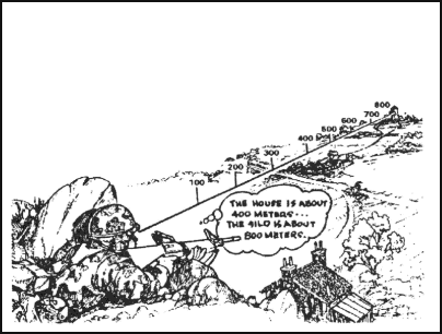
Figure 5-9. Using a 100-meter unit-of-measure method.
(2) Flash-To-Bang Method. To use this method to determine range to an explosion or enemy fire, begin to count when you see the flash. Count the seconds until you hear the weapon fire. This time interval may be measured with a stopwatch or by using a steady count, such as one-thousand-one, one-thousand-two, and so forth, for a three-second estimated count. If you must count higher than 10 seconds, start over with one. Multiply the number of seconds by 330 meters to get the approximate range (FA uses 350 meters instead).
(3) Proficiency of Methods. The methods discussed above are used only to estimate range (Table 5-1). Proficiency in both methods requires constant practice. The best training technique is to require the soldier to pace the range after he has estimated the distance. In this way, the soldier discovers the actual range for himself, which makes a greater impression than if he is simply told the correct range.
Factors Affecting Range Estimation
Factors Causing Underestimation of Range
Factors Causing Overestimation of Range
The clearness of outline and details of the object.
When most of the object is visible and offers a clear outline.
When only a small part of the object can be seen or the object is small in relation to its surroundings.
Nature of terrain or position of the observer.
When looking across a depression that is mostly hidden from view.
When looking downward from high ground.
When looking down a straight, open road or along a railroad.
When looking over uniform surfaces like water, snow, desert, or grain fields.
In bright light or when the sun is shining from behind the observer.
When looking across a depression that is totally visible.
When vision is confined, as in streets, draws, or forest trails.
When looking from low ground toward high ground.
In poor light, such as dawn and dusk; in rain, snow, fog; or when the sun is in the observer’s eyes.
Light and atmosphere
When the object is in sharp contrast with the background or is silhouetted because of its size, shape, or color.
When seen in the clear air of high altitudes.
When object blends into the background or terrain.
Table 5-1. Factors of range estimation.
Land Navigation Training Software
- Chapter 1: TRAINING STRATEGY
- Chapter 2: MAPS
- Chapter 3: MARGINAL INFORMATION AND SYMBOLS
- Chapter 4: GRIDS
- Chapter 5: SCALE AND DISTANCE
- Chapter 6: DIRECTION
- Chapter 7: OVERLAYS
- Chapter 8: AERIAL PHOTOGRAPHS
- Chapter 9: NAVIGATION EQUIPMENT AND METHODS
- Chapter 10: ELEVATION AND RELIEF
- Chapter 11: TERRAIN ASSOCIATION
- Chapter 12: MOUNTED LAND NAVIGATION
- Chapter 13: NAVIGATION IN DIFFERENT TYPES OF TERRAIN
- Chapter 14: UNIT SUSTAINMENT
- Appendix A: FIELD SKETCHING
- Appendix B: MAP FOLDING TECHNIQUES
- Appendix C: UNITS OF MEASURE AND CONVERSION FACTORS
- Appendix D: JOINT OPERATIONS GRAPHICS
- Appendix E: EXPORTABLE TRAINING MATERIAL
- Appendix F: ORIENTEERING
- Appendix G: M2 COMPASS
- Appendix H: ADDITIONAL AIDS
- Appendix I: FOREIGN MAPS
- Appendix J: GLOBAL POSITIONING SYSTEM
- Appendix K: PRECISION LIGHTWEIGHT GLOBAL POSITIONING SYSTEM RECEIVER
- Map Reading and Land Navigation GLOSSARY
- Map Reading and Land Navigation REFERENCES